Connectivity Solutions
Cable Assemblies
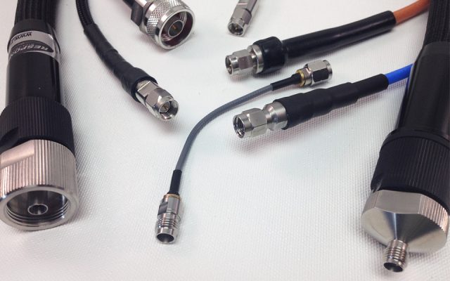
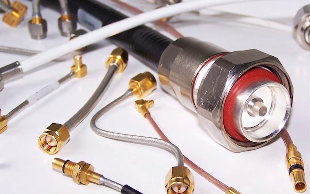
Custom and standard RF cable assemblies built to your electrical and mechanical specification. From flexible low-loss jumpers to ruggedized semi-rigid coax, Response Microwave assembles and tests every cable to guarantee performance from DC through mmWave frequencies.
Build Your Assembly
Cable Assembly Designer
Select your connectors, cable, and length — we'll build it to spec.
Maximum Operating Frequency
Cable Type options below will automatically narrow to those rated at or above this frequency.
Connector A (End 1)
Connector B (End 2)
Length
Options
Live Preview
| Cable | RG-316 · Flexible · DC–3 GHz |
|---|---|
| End A | SMA Male |
| End B | SMA Male |
| Length | 12 in (overall) |
| Testing | Standard (go/no go) |
| Qty | 1 |
Add it to your cart to keep browsing or build another assembly, or email us this one directly.
Email This Request Directly
We'll send your configuration to our sales team and reply to you directly. Fields marked * are required.
Need something specific?
Custom specifications welcome.
If the designer doesn't cover your requirement, please send us a message and/or drawing and our engineers can design a custom solution from prototype through production.
Before You Order
General Considerations
A few factors worth thinking through before you request a quote — electrical, mechanical, and environmental requirements all shape the right cable and connector selection.
Electrical
The operating frequency, insertion loss, VSWR, and power requirements are key factors in determining your optimum assembly, as cable and connector selection will be driven by these elements.
Other factors may be electrical length, phase, or delay time — all of which are directly related to and affected by the selected cable's velocity of propagation and associated operating frequency.
Mechanical
There are several ways to define cable length based on specific application needs:
- Overall — distance from connector end face to connector end face
- Between Connectors — distance from back end of connector to back end of connector
- Reference Plane — distance from connector center line to connector center line
Unless specified otherwise, supplied cables will be based on overall length condition. In any case, specified standard tolerance will apply unless otherwise specified.
Pre-formed cables can be supplied upon receipt of your defined routing for required bends and shapes. Associated tolerances will be discussed during the quote phase, and a mechanical drawing will be presented and/or agreed upon prior to build.
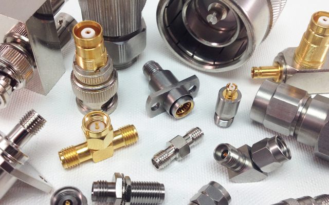
Connector definition is often overlooked but is an integral and important part of your assembly. Please be sure to advise the following elements relative to the required series of Connector A and Connector B of your assembly:
Gender
- Male
- Female
- Reverse Polarity Male
- Reverse Polarity Female
Configuration
- Straight
- Right Angle
- Bulkhead
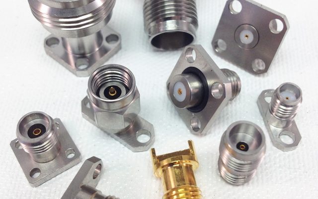
- Flanged (2 or 4 hole)
It is also important to specify the required orientation of any D-flats and right angles of a given connector relative to the corresponding connector.
Environmental
All cables are not created equally, so please make us aware of any special requirements based on the environment your cable will ultimately be exposed to, so proper materials and conditioning can be considered.